Solidworks
Overview:
SolidWorks is a solid modeling computer-aided design (CAD) and computer-aided engineering (CAE) computer program. SolidWorks currently markets several versions of the SolidWorks CAD software in addition to eDrawings, a collaboration tool, and Draft Sight, a 2D CAD product.
Objective:
3D solid modeling is a critical aspect for modern product development and provides the basis for design, simulation, and manufacturing of any part and assembly across a broad range of industries, applications, and products.
Pre-requisite:
Entire program carries modelling and other design applications. Students pursuing diploma and degree programs in mechanical, automobile and aeronautical can enroll in this program.
Duration:
75 Hours.- Sketching Tools
- Editing Tools
- Adding dimensions & Relations
- Blocks concept - Creating& Inserting blocks
- Extrude features, Revolve features
- Hole and its types
- Fillet, Chamfer, Shell, Rib
- Draft, Mirror features, Wrap
- Pattern and its types
- Swept features, Loft features
- Boundary boss feature, Reference Geometries
- Inserting curves
- Inserting Planar Surface, Offset Surface, Radiate Surface
- Extend surface, Surface fill, Ruled Surface
- Trimming Surface, Mid surface, Knit surface
- Replace Face, Delete face, Untrim surface
- Freeform, Thicken, Thicken cut, Cut with Surface
- Inserting and Creating components, Move and Rotate components
- Applying Standard Mates
- Applying Mechanical Mates, Applying Smart mates
- Assembly design practice
- Pattern components
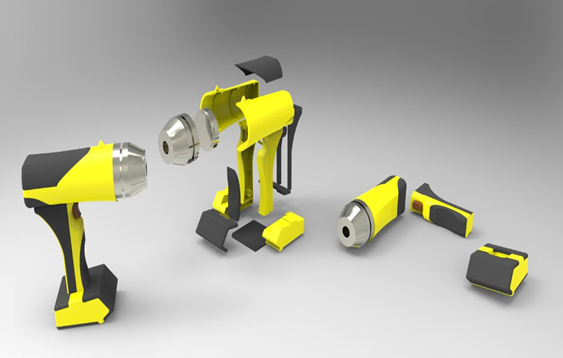
- Creating exploded views, Top down approach
- Creating user defined profile for structural member, Inserting Structural Member
- Inserting Gusset, Fillet Bead, End cap, Mirror
- Extruded Bose/Base, Trim/Extend, Placing Holes, Cut List
- Base Flange/Tab, Edge Flange
- Conversion of Solid Body To Sheet Metal, Miter Flange, Swept Flange
- Jog, Hem, Corners
- Rip, Sketched Bend, Fold/Unfold
- Cross Break, Lofted Bend, Flatten
- Forming Tools, Inserting Sheet Metal Gusset
- Adding Corner Trim, Lofted Trim, Bend Table
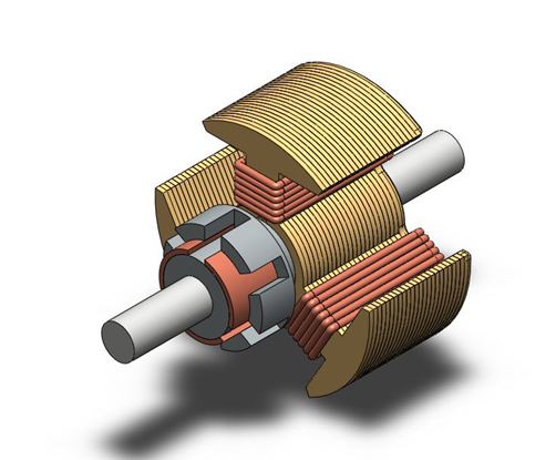
- Generating Views (Projection, Sectional & Detailed, Auxiliary & Break out views)
- Creating Dimensions, Creating GD&T Symbols On Drawings
- Creating Balloons, Bill Of Materials
Sketcher tools:
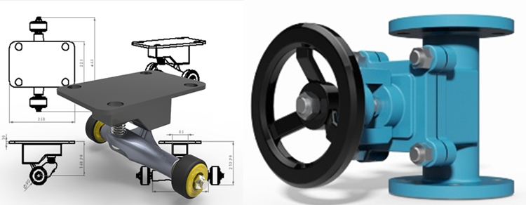
Part & Surface Modeling:
Assembly Modeling:
Weldments:
Sheet metal design:
Generative Drawing Views:
Benefits of getting training with LCT
- Learning from certified instructors.
- Program will be carried on both student and industrial basis.
- Certification from cadd technologies school design private limited.
- Students will be offered with worthy work book
Course Outcome
- Student will learn to sketch with accurate dimensions and study engineering drawings.
- Student will understand 3D views and make 3D models with accurate specifications and features.
- Student will create assembly components by understanding constraints and GD&T concepts.
- Student will learn to produce industry drawings for their productive models.
- Student will be innovative and get updated in their technical skills and will be capable of facing interviews.